3. First Time Setup and First Use
A new TrakStation and TrakPod(s) will require a short procedure to align the units for your environment. Plan on spending about 15 minutes the first day and 15 minutes the second day for setup activities.
Components
TrakStation
- Quick Reference Guide Startup Sheet
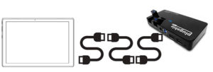
- Tablet
- Power Supply
- 10 port USB Hub
- Power Supply
- USB cable
- Magnetic Mounting hardware
- 3x Magnetic Cloops for cable management
- USB Drive
- 2x USB extension cables
- 1x USB type C adapter (for Microsoft Surface and Lenovo only)
- 1x USB type C to barrel plug adapter (for Lenovo only)
- 1 x tablet keyboard (for Lenovo only)
TrakPod (Cabinet Style)
- Quick Reference Guide startup sheet
- TrakPod
- Mini USB Cable
- 1x Magnetic Cloop for cable management
TrakPod (Benchtop Style)
- Fully integrated into your benchtop incubator, just connect a Mini USB Cable
Setup
![]() CAUTION: Please watch the support video to see the step-by-step instructions for initial set-up. Unpack the box and verify that all parts are present and in good condition.
CAUTION: Please watch the support video to see the step-by-step instructions for initial set-up. Unpack the box and verify that all parts are present and in good condition.
1. Option For Keyboard Attachment: Connect power to the TrakStation tablet and turn on tablet power.

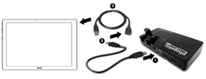
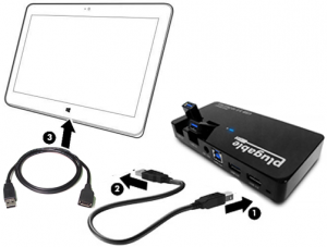
Pictured: TrakStation Setup For Connections (Microsoft Surface top, Lenovo bottom) |
|---|

Option To Mount Tablet Without Keyboard: Mount the TrakStation in a convenient location for the incubators you will be monitoring. A magnetic mounting option is provided capable of holding the TrakStation on most stainless-steel incubator doors and sides. If the magnets are not already applied, affix the two Magic mounts positioned on the back of the TrakStation as pictured below. Clean the TrakStation surface with the provided wipe and press firmly for at least 30 seconds to allow best adhesion of magnets to tablet.
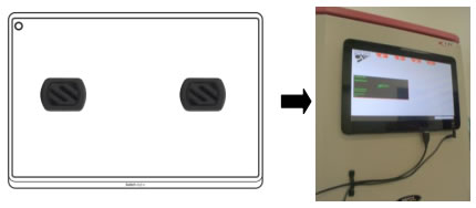 Pictured: Magic Mounts on Back of TrakStation |
|---|
If needed, use the additional metal plates pictured below to affix to the incubator for better magnetic strength.

Pictured: Magic Mount Metal Plates
|
2. Plug the power supply in for the TrakStation (B) and turn on the TrakStation tablet (C). The automatic start of TrakStation interface after windows boot up may take a few minutes.
3. Connect power to the USB Hub
 Pictured: Connections For USB Hub to Power Source |
|---|
![]() CAUTION: Your laboratory setup may require the use of extension cables. If a USB cable longer than 6 feet (1.8 meters) is needed, an active repeater is required on extension cables.
CAUTION: Your laboratory setup may require the use of extension cables. If a USB cable longer than 6 feet (1.8 meters) is needed, an active repeater is required on extension cables.
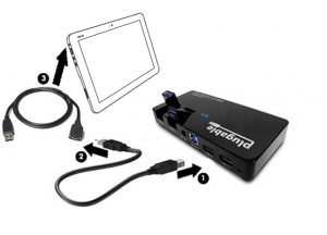
4. Plug the 10 port USB Hub into the TrakStation (A) using the USB cable, one of the USB extension cables and if applicable a USB type C adapter. The USB Hub can be located out of the way either behind or on top of the incubator. See below for proper USB HUB setup by tablet model type. Optional: For 1 TrakPod use USB-C adapter to connect the TrakPod directly.
 Pictured: Lenovo / MS Surface to USB Hub Pictured: Lenovo / MS Surface to USB Hub |
Pictured: Acer to USB Hub |
|---|---|
Pictured: ASUS to USB Hub |
Pictured: HP to USB Hub |
5. If desired, plug a second USB extension cable into the USB Hub and position it for easy access connection of a USB drive (customer supplied) to download data. Data can be retrieved by connecting the TrakStation to the local internet if applicable or downloaded as a CSV file to an external USB. See the Menu Functions Section for instructions to retrieve data (specifically the Pod Page and Remote Access).
|
Pictured: USB Drive Connected to Hub |

6. For Cabinet Style incubators, feed the TrakPod fiber optic cable into the access port of your incubator.
![]() CAUTION: In order to prevent the fiber optic from being pinched by the self, feed the cable down through a hole in the shelf and gently loop it back up. Post-installation be sure to remove the TrakPod cabling from the incubator shelf while moving any of the shelves.
CAUTION: In order to prevent the fiber optic from being pinched by the self, feed the cable down through a hole in the shelf and gently loop it back up. Post-installation be sure to remove the TrakPod cabling from the incubator shelf while moving any of the shelves.
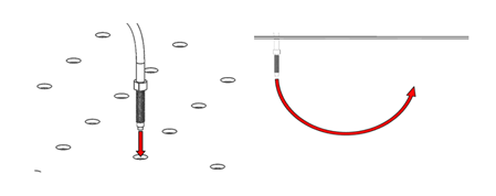
Pictured: Fiber Optic Cable Routing |

7. Choose one of the middle shelves in the incubator and mount the fiber optic fixture onto the shelf of the incubator. Loosely assemble the fixture to the supplied wingnut and fiber optic cable. Then screw the fixture all the way onto the fiber optic and tighten the wingnut to hold it in place on the incubator shelf.
|
Pictured: Fixture Installed on Incubator Shelf |

8. Cut the stopper for the access port in such a way that the fiber optic can be placed into the stopper and seal the access port of the incubator. A slit or wedge cut is recommended.
|
OR
Pictured: Modified Stoppers |


9. Place the TrakPod onto the side of the incubator using the internal magnets to hold the TrakPod on the incubator. Use the magnetic Cloops as needed to keep the USB cables in place and tidy.
 Pictured: Trakpod Mounted on Incubator |
 |
|
10. Plug in the USB cable between the TrakStation’s USB Hub and TrakPod. For Benchtop Style incubators: The TrakPod is already installed inside the incubator (if available). Plug in the USB cable between the TrakStation’s USB Hub and the designated USB port on the back of the incubator.
|
Pictured: Cabinet TrakPod to USB Hub Connection |

Optional: Use a USB extension cable as necessary to cover longer distances between the TrakStation and TrakPod.
If a USB cable longer than 6 feet (1.8 meters) is needed, an active repeater is required on extension cables.
|
Pictured: Benchtop TrakPod to USB Hub |

11. On the TrakStation user interface, navigate to the Add/Remove Pods menu in ‘Settings’ and find the serial number of the newly-plugged-in Pod to add it to the TrakStation display. For each connected TrakPod, a user-specified name can be assigned such as an incubator number or identification that is going to be used.
12. Repeat steps 6 through 11 as necessary for additional TrakPods (up to eight (8) per TrakStation).
![]() CAUTION: TrakPods should be connected, added, and assigned one at a time for optimal results.
CAUTION: TrakPods should be connected, added, and assigned one at a time for optimal results.
First Use
The first time you use the TrakStation, the date and time should be checked and if needed, adjusted.
![]() CAUTION: Windows Operating System tablet date, time, and network connections are configured at the operating system level. Adjusting other settings is not advised except at your own risk.
CAUTION: Windows Operating System tablet date, time, and network connections are configured at the operating system level. Adjusting other settings is not advised except at your own risk.
![]() CAUTION: A new TrakStation will also need to have the qc2 alignment tool assigned to it. These can both be performed in the Supervisor Screen (see Menu Functions Section Supervisor Screen). Check that the dashes are included in the entry of the qc2 alignment tool.
CAUTION: A new TrakStation will also need to have the qc2 alignment tool assigned to it. These can both be performed in the Supervisor Screen (see Menu Functions Section Supervisor Screen). Check that the dashes are included in the entry of the qc2 alignment tool.
Quality Control (QC) Test
When first connected, each TrakPod must have the initial QC test performed. For a full description of QC testing see ‘Routine Operations Workflow – QC Testing’.
![]() CAUTION: Perform the initial QC Test before continuing with Site Standardization.
CAUTION: Perform the initial QC Test before continuing with Site Standardization.
Initial QC Test
- The QC test is run from the Pod menu or the ‘Settings’ menu. Select the Run QC Test option to proceed through the test. NOTE: The FIND FIBER button will cause the Pod to flash the LED several times and allow you to locate which fiber optic might be associated with the chosen Pod.
- Use a lint free tissue like a Kimwipe to remove any dust from the fiber optic surface.
- Place the qc2 alignment tool on the fiber fixture. It can be helpful to apply downward pressure to the qc2 for the test to ensure it is fully seated on the fiber optic fixture.

Pictured: qc2 Alignment Tool on Probe |
- Press the CONTINUE button: The TrakPod will test the fluorescent signal and compare it to the assigned fluorescent levels.
- The Screen will then display the result of the QC Test.
Site Standardization
Site Standardization is a procedure performed on first installation of the TrakStation systems and repeated if culture conditions are altered through a change in culture media, change in incubators, or a physical relocation. The site standardization requires a pH reference sample to complete.
Why is Site Standardization Important?
During TrakPod adjustment at the factory, several environmental factors are different than in clinical laboratory conditions including: CO2, medium composition, temperature, elevation, humidity, the condition of the incubator, and test equipment used by the manufacturer. Site standardization customizes pH monitoring values based on unique embryo culture conditions.
What is a pH Reference Sample?
A pH reference sample is used during site standardization to align pH monitoring to your embryo culture conditions. It uses media used in your lab for embryo culture and allows the TrakStation to determine your unique laboratory pH based on environmental conditions and medium composition. Recommended options for the pH reference sample include:
- One additional disposable sensor with 150µL of IVF medium and sufficient oil to be read using a blood gas analyzer.
- A medium sample created and read similarly to your previously protocol for pH measurement (such as using a pH electrode probe).
- The Certificate of Analysis (CoA) value after duplicating the CO2 settings from the certificate.
![]() CAUTION: We do not recommend solely using the CoA of the media as there is variance between media samples and the location of media manufacture.
CAUTION: We do not recommend solely using the CoA of the media as there is variance between media samples and the location of media manufacture.
How Do I Achieve Maximum System Accuracy?
Ensure that the incubator being used is properly calibrated for both CO2 and temperature. To calibrate, consult the incubator operator’s manual for your specific model. Verify the incubator temperature and CO2 concentration by an external method (i.e. Thermometer, Fyrite) before beginning your setup tests.
![]() CAUTION: If using the CoA as a reference sample, it is also imperative that the incubator be set to the conditions (temperature and CO2 concentration) listed for the certified culture media. If the incubator settings are different than those stated on the CoA, pH values logged by TrakStation may not be the same as listed on the CoA.
CAUTION: If using the CoA as a reference sample, it is also imperative that the incubator be set to the conditions (temperature and CO2 concentration) listed for the certified culture media. If the incubator settings are different than those stated on the CoA, pH values logged by TrakStation may not be the same as listed on the CoA.
At BCSI, the TrakStation system is set for Universal IVF Media, 5% CO2 and 37°C in Seattle, WA USA at an elevation of 46 Feet ASL. A tool to calculate pH changes is located here.
If you are in most any other location or use any other media or have changes to your incubators, you must execute the steps below.
![]() CAUTION: BCSI recommends that you always execute these steps when first setting up the system.
CAUTION: BCSI recommends that you always execute these steps when first setting up the system.
Site Standardization Preparation
- Remove IVF medium and oil from refrigerator and let sit out for a few minutes while getting the sensors ready.
- Remove three (3) sensors aseptically from the sterilization pouches in which they arrived and place the sensors in a petri dish or rack. Sensors should be easily removable from the holder to minimize the time that the incubator is open when reading the sensors.
- Prepare the pH Reference Sample (see What is a pH Reference Sample? for recommended options).
- Hold the sensor with the opening upward. Carefully pipette 100 µL of media down the side of the sensor. Avoid adding bubbles while doing this step. Also avoid touching the pipette tip to the membrane.
- Pipette oil onto each of the sensors. BCSI recommends using 50 µL for Humid Incubators, and 150 µL for Dry Incubators. Touch the tip of the pipette above the surface of the medium and flow the oil onto the surface of the medium avoiding bubbles. It should spread out and completely cover the surface of the medium.

Pictured: Sensor Preparation With Media and Oil
CAUTION: It is critical to allow the sensors to equilibrate for a full 24 hours prior to performing site standardization. Avoid opening the incubator more than necessary during this initial equilibration time. - Place all sensors in the incubator and let sit for 24 hours. Settings should be your normal CO2 levels and normal temperature near 37 ⁰C.

Site Standardization Readings
- To read the pH Reference Sample, have your external pH measurement tool calibrated and ready to read.
- Remove your Reference Sample from the incubator and quickly (within 30 seconds) read the pH value. Record or remember the reference sample pH for use later in site standardization. It is recommended to place the tip of the index finger over the top of the container or cap it while carrying it to the instrument. This will keep the pH as stable as possible in the lab atmosphere.
- Using the Site Standardization menu tool for the specific TrakPod, Enter the pHID for the sensors being used. A lot specific pHID is printed on the blue kit packaging (25050 in the example below). Use the pHID on your kit packaging when setting up to read the pH.
|
Pictured: Example Sensor Label |

![]() CAUTION: The pHID 25050 is an example pHID used only for demonstration. Do not enter 25050 as your pHID for testing purposes.
CAUTION: The pHID 25050 is an example pHID used only for demonstration. Do not enter 25050 as your pHID for testing purposes.
|
Pictured: Site Standardization Screen |

- Measure each (1) sensor once in the incubator. Press the sensor into the fixture making sure the sensor is fully seated in the fixture. Keep index finger covering the top of the sensor while pushing the Go button on the TrakStation as this lowers the amount of ambient light interacting with the sensor and ensures it is fully seated in the fixture.
![]() CAUTION: Constant opening/closing of the incubator door will lower the temperature and CO2 in the incubator. Read all three (3) sensor readings quickly (within 30 seconds) OR allow time for the incubator and the sensor to re-equilibrate.
CAUTION: Constant opening/closing of the incubator door will lower the temperature and CO2 in the incubator. Read all three (3) sensor readings quickly (within 30 seconds) OR allow time for the incubator and the sensor to re-equilibrate.
- Upon completing the readings, use the checkboxes to select pH results from your sensor readings to average and push the average button. Do not select a reading if there was an issue with that reading.
Pictured: Site Standardization Screen Continued - Enter your reference pH. The software will calculate your offset and allow you to SET it for the TrakPod.
Pictured: Site Standardization screen continued
- If sensors are to be re-read on a different TrakPod, place the sensors back into the incubator and allow them to re-equilibrate at temperature and CO2. Re-equilibration is essential for accuracy. The sensor out of the incubator slowly changes the pH levels because of temperature decreases- if you repeatedly read the sensor outside of the environment you will get varied results.


NOTE: For multiple incubators, it is not required to use three (3) new sensors for every TrakPod. For example, with four (4) TrakPods, Site Standardization can be performed by equilibrating four (4) sensors all in one incubator. Three (3) or four (4) sensors can be read on the first TrakPod in the equilibrating incubator. The reference pH to enter is the pH measured in that incubator. Then the sensors can be moved quickly to the next incubator. Preferably allow as much time for the sensors to re-equilibrate in the incubator as the time spent moving between incubators. This is for temperature to return to ideal level. Then do site standardization on the second TrakPod. Again, use the pH measured in the first incubator as the reference pH as the sensors’ CO2 levels will not have changed in a short period of time (5 to 15 minutes). Repeat with the third and fourth incubator in the same manner. Finally, place one (1) sensor on each TrakPod and begin monitoring pH for the rest of the week.
This standardization protocol is specific to the media type used. If a different media type is to be used with the TrakStation System you must repeat this protocol for the new media type and adjust your “Offset Values” accordingly.
Why an Offset Value?
Because the setup at BCSI was done under unique conditions, an “Offset Value” is required for every clinic and media type or incubator. This value corrects for the subtle differences between Seattle, WA (where the unit was manufactured) and your clinic. Our Site Standardization protocol assures that the unit is aligned for maximum precision and will match the CoA of the media being used for a specific cycle.